Understanding Cable Management in Data Centers
From a cost perspective, building and operating a data center represents a significant piece of any Information Technology (IT) budget. The key to the success of any data center is the proper design and implementation of core critical infrastructure components. Cabling infrastructure, in particular, is an important area to consider when designing and managing any data center. The cabling infrastructure encompasses all data cables that are part of the data center, as well as all of the power cables necessary to ensure power to all of the loads. It is important to note that cable trays and cable management devices are critical to the support of IT infrastructure as they help to reduce the likelihood of downtime due to human error and overheating.
This article will address the basics of cabling infrastructure and will discuss cabling installation practices, cable management strategies and cable maintenance practices. We will take an in-depth look at both data cabling and power cabling. Let’s begin with a look at the evolution of data center cabling.
DATA CABLING
Ethernet protocol has been a data communications standard for many years. Along with Ethernet, several traditional data cabling practices continue to shape how data cables are deployed.
- High speed data cabling over copper is a cabling medium of choice
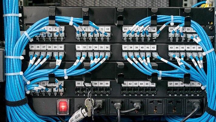
- Cable fed into patch panels and wall plates is common
- The RJ45 is the data cable connector of choice
The functionality within the data cables and associated hardware, however, has undergone dramatic change. Increased data speeds have forced many physical changes. Every time a new, faster standard is ratified by standardization bodies, the cable and supporting hardware have been redesigned to support it. New test tools and procedures also follow each new change in speed. These changes have primarily all been required by the newer, faster versions of Ethernet, which are driven by customers’ needs of more speed and bandwidth. When discussing this, it is important to note the uses and differences of both fiber-optic cable, and traditional copper cable. Let’s compare these two.
Copper cabling has been used for decades in office buildings, data centers, and other installations to provide connectivity. Copper is a reliable medium for transmitting information over shorter distances, but its performance is only guaranteed up to 109.4 yards (100 meters) between devices. (This would include structured cabling and patch cords on either end.) Copper cabling that is used for data network connectivity contains four pairs of wires, which are twisted along the length of the cable. The twist is crucial to the correct operation of the cable for the purposes of canceling out electromagnetic interference (EMI) from external sources and cross talk between adjacent cables.
Copper cables come in two configurations: Solid cables provide better performance and are less susceptible to interference making them the preferred choice for use in a server environment. Stranded cables are more flexible and less expensive and typically are only used in patch cord construction. Copper cabling, patch cords, and connectors are classified based upon their performance characteristics and for which applications they are typically used. These ratings, called categories, are spelled out in the TIA/EIA 568 Commercial Building Telecommunications Writing Standard.

Fiber-optic cable is another common medium for providing connectivity. Fiber cable consists of five elements. The center portion of the cable, known as the core, is a hair-thin strand of glass capable of carrying the light. This core is surrounded by a thin layer of slightly purer glass, called cladding, that contains and refracts that light. Core and cladding glass are covered in a coating of plastic to protect them from dust or scratches. Strengthening fibers are then added to protect the core during installation. Finally, all of these materials are wrapped in plastic or other protective substance that serves as the cable’s jacket.

A light source, blinking billions of times per second, is used to transmit data along a fiber cable. Fiber-optic components work by turning electronic signals into light signals and vice versa. Light travels down the interior of the glass, refracting off of the cladding and continuing onward until it arrives at the other end of the cable and is seen by receiving equipment. When light passes from one transparent medium to another, like from air to water, or in this case, from the glass core to the cladding material, the light bends. A fiber cable’s cladding consists of a different material from the core — in technical terms, it has a different refraction index — that bends the light back toward the core. This phenomenon, known as total internal reflection, keeps the light moving along a fiber-optic cable for great distances, even if that cable is curved. Without the cladding, the light would leak out.

Fiber cabling can handle connections over a much greater distance than copper cabling, 50 miles (80.5 kilometers) or more in some configurations. Because light is used to transmit the signal, the upper limits of how far a signal can travel along a fiber cable are related not only to the properties of the cable but also to the capabilities and relative location of transmitters.
Besides distance, fiber cabling has several other advantages over copper
- Fiber provides faster connection speeds
- Fiber is not prone to electrical interference or vibration
- Fiber is thinner and light-weight, so more cabling can fit into the same size bundle or limited spaces
- Signal loss over distance is less along optical fiber than copper wire
Two varieties of fiber cables are available in the marketplace: multimode fiber(MMF) and single mode fiber(SMF). Multimode is commonly used to provide connectivity over moderate distances, such as those in most data center environments, or among rooms within a single building. Single mode fiber is used for the longest distances, such as among buildings on a large campus, or between sites. Copper is generally the less expensive cabling solution over shorter distances (i.e. the length of data center server rows), while fiber is less expensive for longer distances (i.e. connections among buildings on campus).

MODULARITY
Modularity(It is one measure of the structure of networks. It was designed to measure the strength of division of a network into modules) is an important concept in the contemporary data center. Modular, scalable Network Critical Physical Infrastructure (NCPI) components have been shown to be more efficient and more cost effective. The data cabling industry tackled the issue of modularity decades ago. Before the patch panel was designed, many adds, moves, and changes were made by simply running new cable. After years of this ‘run a new cable’ mentality, wiring closets and ceilings were loaded with unused data cables. Many wiring closets became cluttered and congested. The strain on ceilings and roofs from the weight of unused data cables became a potential hazard. The congestion of data cables under the raised floor also impeded proper cooling and exponentially increased the potential for human error and downtime.
In the realm of data cabling, the introduction of the patch panel brought an end to the ‘run a new cable’ philosophy and introduced modularity to network cabling. The patch panel, located either on the data center floor or in a wiring closet, is the demarcation point where end points of bulk cable converge. If a data center manager were to trace a data cable from end to end, starting at the patch panel, he would probably find himself ending at the wall plate. This span is known as the backbone.

The modularity of the system is in the use of patch cables. The user plugs his patch cable into a wall plate. If he needs to move a computer, for example, he simply unplugs his patch cable and connects it into a different wall plate. The same is true on the other end, back at the patch panels. If a port on a hub or router malfunctions, the network administrator can simply unplug it and connect it into another open port.
Data center backbone cabling is typically designed to be non-scalable. The data cabling backbone, 90% of the time, is located behind the walls, not out in the open. Typically a network backbone, when installed, especially in new construction scenarios, accounts for future growth considerations. Adds, moves, and changes can be very costly once the walls are constructed. In new construction, it is best to wire as much of the building as possible, with the latest cable standard. This reduces expenses once the walls are constructed.
Now that we have discussed the concept of modularity, let’s overview the different types of data cables that exist in a data center.
So, what are the different types of common data center specific data cables?
Category 5 (Cat 5) was originally designed for use with 100 Base-T. Cat 5e supports 1 Gig Ethernet. Cat 6a supports 10 Gig Ethernet. It is important to note that a higher rated cable can be used to support slower speeds, but the reverse is not true. For example, a Cat 5e installation will not support 10 Gig Ethernet, but Cat 6a cabling will support 100 Base-T. Cable assemblies can be defined as a length of bulk cable with a connector terminated onto both ends. Many of the assemblies used are patch cables of various lengths that match or exceed the cabling standard of the backbone. A Cat 5e backbone requires Cat 5e or better patch cables.
Data center equipment can require both standard and custom cables. Some cables are specific to the equipment manufacturer. One example of a common connection would involve a scenario in which a Cisco router with the 60-pin LFH connector connected to a router with a V.35 interface requires an LFH60 to V.35 Male DTE cable.
An example of a less common connection would be a standalone tape backup that may have a SCSI interface. If the cable that came with the equipment does not match up to the SCSI card in a computer, the data center manager will find himself looking for a custom SCSI cable.
A typical example of the diversity of cables required in the data center is a high speed serial router cable. In a wide area network (WAN), routers are typically connected to modems, which are called DSU/CSU’s. Some router manufacturers feature unorthodox connectors on their routers. Depending on the interface that the router and DSU/CSU use to communicate with one another, several connector possibilities exist. Other devices used in a computer room can require any one of a myriad of cables. Common devices besides the networking hardware are telco equipment, KVM’s, mass storage, monitors, keyboard and mouse, and terminal servers. Sometimes brand-name cables are expensive or unavailable. A large market of manufacturer equivalent cables exists, from which the data center manager can choose.
Now that we’ve talked about a basic overview of both power and data cabling, let’s take a look at some best practices for cabling in the data center.
Some best practices for data cabling include:
- Cable ties
Overhead cables that are in large bundles should run in cable trays or troughs. If the manufacturer of the tray or trough offers devices that keep the cable bend radius in check then they should be used as well. Do not over tighten tie-wraps or other hanging devices. It can interfere with the performance of the cable.

• Cable bend radius
Cables are composed of different components that may become compromised if bent too far and stress is placed on the cable. For example, while bending a medium-voltage cable consisting of a copper tape shield, the cable may form cracks in the outer jacket. To prevent cable damage, cable standards such as The National Electrical Code (NEC) and the Insulated Cable Engineers Association (ICEA) formed requirements for minimum bend radius(smallest allowed radius the cable is allowed to be bent around). Be cognizant of the cable’s bend radius specifications and adhere tightly to them. Do not over tighten tie wraps. This can interfere with the performance of the cable. The bend radius are determined by industry standards and vary depending on the cable type. I would recommend you to have a look at this article by Anixter to understand more about it.

• Vertical/Horizontal Cable Management
Use vertical and/or horizontal cable management to take up any extra slack. Vertical cable management is when you run the cables from a piece of equipment within a server rack over to a vertical cable manager. This cable manager mounts within the rack and keeps cables bundled together while they travel up or down until they exit the rack. They come in several sizes so you can fit as many cables as you need to meet your specific situation. In addition, it allows the cables to bend safely when they exit the rack or go back toward another piece of equipment and it doesn’t take up equipment space. Horizontal cable management is when you run the cables through a plastic or metal unit that is placed above or below the device where the cables are plugged. The cables are kept in place and separated so each one has its own spot within the cable manager. These cable managers can come in 1U or 2U size options so they can organize cables from multiple devices. The advantages of horizontal cable management include easier to trace cables, easier to add/remove cables and cables are protected and organized at all times.

Cable management methods & tools that are used are not limited to this, read through my other article about cable management systems to understand more about these techniques.
• Testing cables
There are several manufacturers of test equipment designed specifically to test today’s high speed networks. Make sure that the installer tests and certifies every link. A data center manager can request a report that shows the test results.
Are there any common practices that should be avoided? When designing and installing the network’s backbone care should be taken to route all Unshielded Twisted Pair (UTP is the U.S. standard) or Shielded Twisted Pair (STP is the European standard) cables away from possible sources of interference such as power lines, electric motors or overhead lighting. Read the articles about the different methods and technics of testing fiber optic cables.
The next thing that we need to consider is related to the power cable management and best practices scenarios related to both data and power cables which I have covered in the second article. I would strongly recommend you to review the same to have a complete idea about the cabling strategies.
Have a comment or points to be reviewed? Let us grow together. Feel free to comment.