Fiber optics cable design and data transmission
In my previous article, we have seen different categories of copper twisted pair cables and its features(CAT 6, CAT 7, CAT 8, etc.). From this, we understood that in today’s world the most advanced twisted pair cable(CAT 8) can transfer the data at a speed of 40Gbps. Its good speed, right? Have you also noticed that twisted-pair cable’s data transfer speed is reducing when length increases (single connection can be a maximum of 100 meters)? But is that the only speed and distance that we need to fulfill the requirement of today’s world? The answer is NEVER EVER !!!
There comes the applicability of Fiber optic cables with many advancements to copper twisted pair cables. A fiber-optic cable, also known as an optical-fiber cable, is an assembly similar to an electrical cable, but containing one or more optical fibers that are used to carry light. It has a number of optical fibers bundled together, which are normally covered in their individual protective plastic covers. The optimal size of a single fiber is about just human hair. Compared to copper cables, fiber optic cables provide higher bandwidth and can transmit data over longer distances.
Let us have a look into the physical design of optical fiber cables and how it guides light.
Design concept of optical fiber cables
In a simple word, we can understand the design of a fiber optic cable which can be defined as below,
“Optical fiber consists of a core and a cladding layer, selected for total internal reflection due to the difference in the refractive index between the two”.
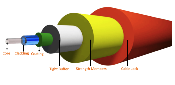
The center of each strand is called the core, which provides the pathway for light to travel. The core is surrounded by a layer of glass called cladding that reflects light inward to avoid loss of signal and allow the light to pass through bends in the cable.
Core: The center of each strand is called the core which provides the pathway for light to travel. It’s made of silica, doped silica or plastic which is the light transmitting region of the fiber.
Cladding: This is the first layer around the core. The core is surrounded by a layer of glass called cladding that reflects light inward to avoid loss of signal and allow the light to pass through bends in the cable. It is also made of silica, but not the same composition as the core. The main function of the cladding is to provide a reflective surface for light. This creates an optical waveguide which confines the light in the core by total internal reflection at the core-cladding interface.
The cladding layer is made of a dielectric material(glass or plastic) to performs the following functions:
- Reduces loss of light from the core into the surrounding air.
- Reduces scattering loss at the surface of the core.
- Protects the fiber from absorbing surface contaminants.
- Adds mechanical strength.
Coating: The coating is the first non-optical layer around the cladding. The coating typically consists of one or more layers of polymer that protect the silica structure against physical or environmental damage. The coating is stripped off when the fiber is connectorized or fusion spliced.

Those three are the major components in fiber design and there can be some additional coatings over it to operate/protect in multiple scenarios. That additional protection can be as below,
Buffer: The buffer is an important feature of the fiber. It is 900 microns and helps protect the fiber from breaking during installation and termination and is located outside of the coating.
Strength members: Buffer coating surrounded by a protective plastic oversheath containing strength members which, in some cases, are enclosed by a layer of armoring.
Jack: Is the outermost layer for protection usually made up of plastic.

Note: In many scenarios, we often refer coating and buffer layers as same or both in a single design. The difference totally depends on design(water resistance, corrosion-resistant, etc.). Both are providing layers of protection in their own ways.
Principle of light Transmission through Fiber Optics
We have seen the physical structure of a fiber optics cable. Now the consideration would be to transmit the data through it. How’s it possible? What is the method used to transmit the data and how effective it’s to?
In order to understand the fiber optic data transmission, you need to look back to some of the old school physics concepts which are mainly Critical angle, refractive index, and Total Internal Reflection.
Let us consider the scenario that we are flashing a laser light from a glass medium to air. When doing this there are some phenomenon’s which happens in the background.

In order to understand the terms, I would strongly suggest you compare each statement with the picture.
- Here the source light(laser light) is known as the incident ray.
- A medium in which the speed of light is more is known as an optically rarer medium. Air is an optically rarer medium as compared to glass and water.
- A medium in which speed of light is less is known as an optically denser medium. Glass is an optically denser medium as compared to air.
- The incident ray travels from the glass to air and the initial point where the light hits from the glass to air is called a point of incidence.
- A line that drawn a perpendicular to point of incidence is known as normal.
- The angle between normal and point of incidence is known as the angle of incidence.
- After the point of incidence due to the different density of glass and air the incident rays are being refracted(change in direction) when traveling through air and from this point it will be known as refracted rays.
- The angle between normal and refracted rays is known as the angle of refraction.
- However, there are some light rays that have reflected back to glass itself without going out to glass and these rays are known as partially reflected rays.
- The angle between normal and partially reflected rays is known as the angle of reflection.
- As per the law of reflection, the angle of reflection and angle of incidence will be the same.
Let us say that we are using laser light to generate multiple points of incidence by changing the angle of the incident ray.
Critical angle
At some angle when the laser light(incident ray) is hitting from glass to air, the refracted rays will travel through the surface of glass without passing to air. At this point, we can say that the angle of refraction is 90 degrees. The angle of incidence at which the angle of refraction is 90 degrees is known as the critical angle. The critical angle is the smallest angle of incidence that yields total reflection.
Total Internal Reflection
Another light ray(incident ray) is hitting at a point of incidence, with the angle of incidence is higher than critical angle the refracted rays will completely join with reflected rays. i.e. from this point, there won’t be any refracted rays and it will be only reflected rays available since both joined together. This reflected ray is known as a Totally reflected ray. This phenomenon is known as Total Internal Reflection(TIR).
Necessary condition to occur TIR
- The light ray should travel from denser medium to rarer medium(DàR)
- Angle of incidence should be greater than the critical angle
The core and cladding portion of fiber cables are used to achieve total internal reflection.
Refractive index
The refractive index determines how much the path of light is bent or refracted when trying to enter from one medium to another. It gives an indication of the light-bending ability of that medium. Different mediums are having a different refractive index.

How it guides light in optical fiber cable
Where copper cabling uses electric signals to transmit from one end to another, fiber optics use light pulses to accomplish the same purpose. The basic principle is,” when the light signal is trying to transmit from denser medium to rarer medium(core to cladding) with greater angle than critical Angle the total light signals are reflected back to a denser medium(core) itself due to total internal reflection.”
Optical fibers are composed of fine quality glass or quartz(core) and coated with a thin layer of material(cladding). By design the refractive index of core (1.7) is higher than cladding (1.5) due to this when the light is hitting on a core surface it will undergo total internal reflection. Which will result in a reflection of this ray back to another side of the core? On another side, the circumstances are the same so the ray again goes under total internal reflection. By this way light zigzag until the end of this fiber optics cable.

Have a comment or points to be reviewed? Let us grow together. Feel free to comment.