Various Methods of Fiber Optic Cable Testing – Article 1
As the ever-increasing popularity of intensive bandwidth applications, the demand for fiber optic installations and infrastructures has accelerated parallelly. Optical fiber cable thus has possessed a rather essential position in the telecom industry. In today’s fast-paced workplace maximizing productivity is essential. Whether installing new fiber links or troubleshooting an existing network, the faster you can locate a problem, the faster you can fix it. That’s easier said than done when you are faced with a complex network of fibers, connectors and patch cords. There are two major performance issues with the fiber optic data links which are Loss and Dispersion. Loss of optical signal happens when it travels along with optical fiber being attenuated by the fiber or by any connectors that splice in the link. We must have a sufficient amount of power at the receiver side to get a good signal transmission which won’t happen in the case of Loss. Dispersion is that an optical signal gets spread out by the characteristics of optical fiber that is transmitting it. Dispersion is the problem for short multimode links and very long single-mode links.
As a summary of these challenges, we can say that it’s really necessary to test the fiber optic cables after installation. Fiber optic testers include tools and equipment to perform basic inspection and cleaning, basic troubleshooting and verification testers, certification testers, and advanced OTDR testers for troubleshooting and analysis of existing fiber optic cabling. But how to deliver valid optical fiber cable testing? Here can say that there are two tiers of testing available which is Tier 1 and Tier 2.
Let us look into what are the types of testing methods involved in each Tier testing.
Tier 1 Fiber Testing
Tier 1 testing is the minimum level of testing that is required. This level of testing consists of inspecting fiber optic connectors, link attenuation testing, link length and polarity check which are basic testing levels.
1) Fiber Optic Connector Inspection
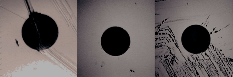
In a study by NTT-Advanced Technology, most installers think that fiber end-face contamination is a major cause of network outages and downtime. Fiber optic inspection enables network technicians and other personnel to safely inspect fiber end-faces for contamination and verify the effectiveness of fiber cleaning procedures. In fiber-optic communication, dust, dirt, oils and anything else on a connector end-face can seriously impact network performance. Even in some dust caps, dust also exists. Except for those contaminants, some accidental behaviors also can cause damage for connecting end-face, which causes network failures too. Seeing is believing. Here are some samples of different contaminants and damage (deep scratch, dirt, and oils).

Dust, oils, and water blocking gel are common forms of fiber connector end-face contamination. Simply touching the ferrule will immediately deposit body oil on the end-face, and cause unacceptable attenuation once the connection is made. Dust and small static-charged particles float through the air and can land on any exposed termination. This can be especially true in facilities undergoing construction or renovation. In new installations, buffer gel and pulling lube can easily find its way onto an end-face.
You know the size of fiber optic cables and it’s inside links. How small it is? So is it really possible to inspect the fiber optics with our bare eyes? The answer is no unless the dirt is big enough for our eyes to catch. But the situation is for even small dirt. Here we have the solution to achieve this inspection which is generally called a Fiber optic microscope. A fiber optic microscope is a type of microscope designed for fiber optic equipment to check unmated fiber optic connectors for dirt and end-face quality.
A fiber optic microscope usually has three major components: an illuminator, a microscopic lens system, and a visual display. The illuminator is used to project light through the optic fibers so any debris or imperfections are visible. The microscope system is to magnify the image of the optic fiber. And the picture will be shown on the display, usually an LED screen.
Microscopes can be divided into two basic groupings: optical and video. Optical microscopes incorporate an objective lens and an eyepiece lens to allow you to view the end-face directly through the device. Video microscopes incorporate both an optical probe and a display for viewing the probe’s image. Probes are designed to be small so that they can reach ports in hard-to-access places. The screens allow images to be expanded for easier identification of contaminants and damage. Because the end-face is viewed on a screen instead of directly, probes minimize the chance of a harmful laser light reaching a person’s eye. Based on these two categories microscopes are designed and namely Desktop Type and Handheld type. Here desktop type is the one for Video microscope and optical type is the one for handheld microscopes.
Video Microscope – Desktop Fiber Optic Microscope
A desktop fiber optic microscope has a free-standing monitor display connected to a separate microscope system, which is useful for high-volume testing or detailed inspection. Like the desktop video three-dimensional microscope, apart from the features mentioned above, it has a focusing wheel, indicator lights, and X/Y axis adjusting knob, which help it have a high performance in fiber optic inspection. And finished, semi-finished, PC and APC all types can be tested with this microscope.

Optical Microscope – Handheld Fiber Optic Microscope
A handheld fiber optic microscope is like a mini version of the desktop type. It fits most of the features of a desktop model into a smaller, portable package. The display and illuminator are combined into one unit, which makes it suitable for on-site inspection and in cases when testing is not regularly controlled. The following picture shows an FFOI-605 handheld fiber optic inspection probe microscope. It is used to examine installed fiber terminations or ensure terminations are smooth and clean. The most brilliant feature of this microscope is that it eliminates the need to access the backside of patch panels or disassemble hardware devices prior to inspection.

Cleaning Fiber Optic Cables
The best solution for any dust, oils, and water blocking gel that is found through microscopes is cleaning. Because cleaning has been part of fiber optic cable maintenance for years, most people have their own approaches for cleaning end-faces, including some suboptimal approaches such as blasting the fiber optic cable with canned air* or using Isopropyl alcohol (IPA)**. Fiber specific solvents are superior at dissolving virtually any contaminate lurking on a fiber end-face and have tailored evaporation rates that give them time to work yet disappear before mating. The most basic tools used are wipes and swabs used to clean patch cords and inside ports, respectively. Convenient fiber optic cleaning kits include all the solvent and cleaning equipment one needs for precision end-face cleaning. The special fiber solvent is perfect for dissolving virtually any contaminant on the fiber end-face and have tailored evaporation rates that give them time to work yet disappear before mating. One-push cleaner is one of the most popular cleaning tool for fiber optic connector (see the picture below).

2) Visual fault locators(VFL) or Visible Light Source Testing
Visual fault locators(VFL) tests optical fiber continuity and this is a type of polarity check. Optical fiber communication systems operate in the infrared region of the electromagnetic spectrum which is invisible to the human eye. However, (red) visible light sources are available for testing and troubleshooting optical fiber systems. In this procedure, we will inject the high power laser lights from one end of the cable and identifies if that signal reaches to other end and if there is any leakage in its pathways. They are also referred to as Visible Light Source testing and visual fault finders. These fault locators will locate visual faults including tight bends, breaks and bad connectors. This device is one of the inexpensive ways to quickly identify faults.

There are varieties of models and manufacturers available in the market. Hence the design, size, and shape of the visual fault locator will be slightly different. These are available with different power ranges specifications and based on this the test distance also will vary. When performing fiber cable testing with a visible light source, you could follow the suggested procedures:
Step 1 – Connect the optical fiber flashlight to one end of a fiber strand (with most units, the fiber must be terminated).
Step 2 – Look at the opposite end and verify if the light is visible. If your cable is not terminated you can inspect full-length cable itself and you can see any if there is any leakage. (Note: Be careful, do not to look directly at active optical fiber strands. Laser light sources can cause serious eye damage)
Step 3 – If the light is not visible at the opposite end, a break or other problem is likely to present somewhere along the length of the fiber. In many instances, the fault location will glow red from the light of the visible light source.
Having a look at these videos would be much recommended if you are the first time in this area. How to Use Visual Fault Locator (VFL) to Find Breaks in Fiber Cable?
That’s not the end 😀 . We have a few more testing techniques to explore and read through article 2 to know more.
Familiarizing the terms
There are some specific terms that are used in this article which may not be well known to you. However, I believe that having the basic idea of these terms can help you a lot to understand the entire contents. Various terms are written here.
* – Canned air is a product used for cleaning or dusting electronic equipment and other sensitive devices that cannot be cleaned using water. The products are most often a can that, when a trigger is pressed, blasts a stream of compressed gas through a nozzle.
** – Isopropyl alcohol (IPA) is a colorless, flammable chemical compound with a strong odor. This is used to clean a variety of substrates and remove a variety of soils.
^ – Polarity check – Polarity is often used to define a direction of flow. In fiber optics, polarity defines the direction the light signal travels through optical fiber.
Have a comment or points to be reviewed? Let us grow together. Feel free to comment.