Understanding Power Cable Management in Data Centers
Cable management is essential to create a visually pleasing and clean work environment. Managing cables or wires helps to maintain basic functionality and also protects the devices from the clogged airflow due to unorganized and disordered wires. Tangled Wires or Cables are generally time-consuming to untangle. We have covered some of the major points related to the basics of data cable management in the previous article and this is the second part of the discussion about the basics of power cable management in a data center and some best practice scenarios where both data cables and power cables are managed.
POWER CABLING
In the case of data center power cabling, historical changes have taken a different route. In traditional data centers, designers and engineers were not too concerned with single points of failure. Scheduled downtime was an accepted practice. Systems were periodically taken down to perform maintenance and to make changes. Downtime is not as accepted as it once was in the data center. In many instances, it is no longer possible to shut down equipment to perform maintenance. A fundamentally different philosophical approach is at work. Instead of the large transformers of yesterday, smaller ones, called power distribution units (PDUs) are now the norm. These PDUs have moved out of the back room, onto the raised floor, and in some cases, are integrated into the racks. These PDUs feed the critical equipment. This change was the first step in a new way of thinking, a trend that involved getting away from the large transformer and switchboard panel.
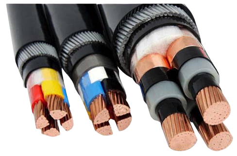
The power cables as the name suggest are used to deliver Electric Power from the generation station ( source) to the next checkpoint ( distribution center, end-user, etc.). we can broadly classify them into AC and DC. Now since our generation is more inclined to AC power we have many more varieties of AC power cables compared to DC. Further classification is made on various parameters like no of phases, length, mode of deployment overhead or underground, shielded or unshielded and even the type of insulation used in them as per application, we can see rubber insulated, PVC insulated, Gas-filled insulation, or liquid (oil) insulation that is chosen depending on parameters like insulation level and cooling required. If we take multiphase cables we even get assortments like corded, uncorded, bundled or solid core.

Similarly for DC power distribution mostly the classification is due to insulation level and voltage level since no accommodations need to be made due to factors like skin effect and interference reduction in design in case of DC power lines.
Traditional data centers, very often, had large transformers that would feed large uninterruptible power supplies (UPSs) and distribution switchboards. From there, the cables would go to distribution panels that would often be located on the columns or walls of the data center. Large UPSs, transformers, and distribution switchgear were all located in the back room. The incoming power was then stepped down to the correct voltage and distributed to the panels mounted in the columns. Cables connected to loads, like mainframe computers, would be directly hardwired to the hardware. In smaller server environments, the power cables would be routed to power strips underneath the raised floor. The individual pieces of equipment would then plug into those power strips, using sleeve and pin connectors, to keep the cords from coming apart.

Modern data centers also have dual cord environments. Dual cord helps to minimize a single point of failure scenario. One of the benefits of the dual cord method is that data center operators can perform maintenance work on source A, while source B maintains the load. The server never has to be taken offline while upstream maintenance is being performed. This trend began approximately 10 years ago and it was clearly driven by the user. It became crucial for data center managers to maintain operations 24 hours a day, 7 days per week. Some of the first businesses to require such operations were the banks, who introduced ATMs, which demanded constant uptime. The customer said, “We can no longer tolerate a shutdown”.
When discussing data center power cabling, it is important to note that American Wire Gauge (AWG) copper wire is the common medium for transporting power in the data center. This has been the case for many years and it still holds true in modern data centers.
The formula for power is Amp x Volts = Power, and data center power cables are delineated by amperage. The more power that needs to be delivered to the load, the higher the amperage has to be. (Note: The voltage will not be high under the raised floor. It will be less than 480V; most servers are designed to handle 120 or 208V.) If the level of power is the same, the amperage and voltage are the same. As the amperage increases or decreases, the gauge of the wire needs to be larger or smaller to accommodate the change in amperage. AWG ratings organize copper wire into numerous recognizable and standard configurations.
A relatively new trend in the domain of data center power cabling is the invention of the power whip. Whips are pre-configured cables with a twist lock cap on one end and insulated copper on the other end. The insulated copper end feeds a breaker in the main PDU; the twist lock end feeds the rack mounted PDU that supplies the intelligent power strips in the rack. Server equipment then plugs directly into the power strip. With whips, there is no need for wiring underneath the floor (with the possible exception of the feed to the main PDU breakers). Thus, the expense of a raised floor can be avoided. Another benefit of whips is that a licensed electrician is not required to plug in the twist lock connectors of the whip into the power strip twist lock receptacles.

Dual cord, dual power supply also introduced significant changes to the data center power cabling scheme. In traditional data centers, computers had one feed from one transformer or panel board, and the earliest PDUs still only had one feed to servers. Large mainframes required two feeds to keep systems consistently available. Sometimes two different utilities were feeding power to the building. Now, many servers are configured to support two power feeds, hence the dual cord power supply. Because data center managers can now switch from one power source to another, this allows for maintenance on infrastructure equipment without having to take servers offline.
It is important to understand that the power cabling requirements to support the dual cord power supply configuration have doubled as a result. The same wire, the same copper, and the same sizes are required as was required in the past, but now data center designers need to account for double the power infrastructure cable, including power related infrastructure that may be located in the equipment room that supports the data center.
Power cabling best practices are described in the National Electric Code (NEC).
When addressing best practices in power cabling, it is important that data center professionals use the term, “continuous load’. The continuous load is defined as any load left on for more than 3 hours, which is, in effect, all equipment in a data center. Due to the requirements of the continuous load, data center operators are forced to take all rules that apply to amperages and wire sizes and de-rate those figures by 20%. For example, if a wire is rated for 100 amps, the best practice is not to run more than 80 amps through it.
Let’s discuss this further. Over time, cables can get overheated. The de-rating approach helps avoid overheated wires that can lead to shorts and fires. If the quantity of copper in the cable is insufficient for the amperages required, it will heat to the point of melting the insulation. If insulation fails, the copper is exposed to anything metal or grounded in its proximity. If it gets close enough, the electricity will jump or arc and could cause a fire to start. Undersized power cables also stress the connections. If any connection is loose, the excess load exacerbates the situation. The de-rating of the power cables takes these facts into account. To further illustrate this example, let’s compare electricity to water. If too much water gets pushed into a pipe, the force of the water will break the pipe if it is too small. Amperages are forcing electricity through the wire; therefore, the wire is going to heat up if the wire is undersized. The manufacturer, or supplier, of the cable, provides the information regarding the circular mill, or the area of the wires, inside the cable. The circular mill does not take into account the wire insulation. The circular mill determines how much amperage can pass through that piece of copper.
Data center operators would also perform infrared scans(thermal imaging or thermography) on power cable connections prior to the shutdowns to determine problem areas. They would then locate the hot spots(inductive heating) that could indicate a possible risk of short circuits, loose/deteriorated connections, overloads, unbalanced loads, open circuits, defective equipment and address them.

Whether you’re dealing with wire loom, cable trays or heavy-duty cord protectors, one of the cardinal rules of installation is to never overstuff a cable management device with cables. By exceeding fill capacity, you run the risk of crush-related attenuation, insulation damage, crosstalk, and even – in the case of power cables – overheating and fire. Professional installations using duct, conduit or cable trays should consult TIA/EIA, NEC and/or manufacturers’ guidelines for product-specific fill capacity specs.
Now let us compare some best practice scenarios where both data cables and power cables are managed,
Let’s compare overhead and under the floor installations.
The benefit of under the floor cabling is that the cable is not visible. Many changes can be made and the wiring will not be seen. The disadvantage of under the floor cabling is the significant expense of constructing a raised floor. Data center designers also need to take into account the danger of opening up a raised floor and exposing other critical systems like the cooling airflow system, if the raised floor is used as a plenum.
With overhead cabling, data center designers can use cabling trays to guide the cables to the equipment. They can also run a conduit from the PDU directly to the equipment or computer load. The conduit is not flexible, however, which is not good if a constant change is expected. A best practice is to use overhead cables which are all pre-configured in the factory and placed in the troughs to the equipment. This standardization creates a more convenient, flexible environment for the data center of today.
Where your power source is, where the load is, and what the grid is like, all affect the design and layout of the cabling in the data center. When discussing overhead cabling, data centers designers are tasked with figuring out the proper placement of cables ahead of time. Then, they can decide if it would be best to have the troughs directly over the equipment or in the aisle. Also, designers have to take into account local codes for distributing power. For example, there are established rules that require that sprinkler heads not be blocked. If there is a 24 inch (60.96 cm) cable tray, designers could not run that tray any closer than 10 inches (25.4 cm) below the sprinkler head to cover up or obstruct the head. They would need to account for this upfront in the design stage.
Now that we’ve touched upon best practices for installation, let’s discuss some strategies for selecting cabling topologies related to power and data cables.
Network Topology deals with the different ways computers (and network enabled peripherals) are arranged on or connected to a network. The most common network topologies are:
Star – All computers are connected to a central hub.
Ring – Each computer is connected to two others, such that, starting at any one computer, the connection can be traced through each computer on the ring back to the first.
Bus – All computers are connected to a central cable, normally termed bus or backbone.
Tree – A group of start networks are each connected to a linear backbone.
For data cabling, in IEEE 802.3, UTP/STP Ethernet scenarios, a star network topology is used. Star topology implies that all computers are connected to a central hub. In its simplest form, a UTP/STP Ethernet Star topology has a Hub at the center and devices (i.e. personal computers, printers, etc.) connected directly to it. Small LANs fit this simple model. Larger installations can be much more complicated, with segments connecting to other segments, but the basic Star topology remains intact.
Power cables can be laid out either overhead in troughs or below the raised floor. Many factors come into play when deciding on a power distribution layout from the PDUs to the racks. The size of the data center, the nature of the equipment being installed and the budget are all variables. However, be aware that two approaches are commonly utilized for the distribution of power cables in the data center.
One approach is to run the power cables inside conduits from large wall mounted or floor mounted PDUs to each cabinet location. This works moderately well for a small server environment with a limited number of conduits. This does not work well for larger data centers when cabinet locations require multiple power receptacles.
Another approach, more manageable for larger server environments, is the installation of electrical substations at the end of each row in the form of circuit panels. Conduit is run from power distribution units to the circuit panels and then to a subset of connections to the server cabinets. This configuration uses a shorter electrical conduit, which makes it easier to manage, less expensive to install, and more resistant to a physical accident in the data center. For example, if a heavy object is dropped through a raised floor, the damage it can cause is greatly reduced in a room with segmented power, because fewer conduits overlap one another in a given area.
Even more efficient is to deploy PDUs in the racks themselves and to have whips feed the various racks in the row.
What are the best practices for cable management and organization techniques?
Some end users purchase stranded bulk data cable and RJ45 connectors and manufacture their own patch cables on sight. While doing this assures a clean installation with no excess wire, it is time consuming and costly. Most companies find it more prudent to inventory pre-made patch cables and use horizontal or vertical cable management to take up any excess cable. Patch cables are readily available in many standard lengths and colors.
Are there any common practices that should be avoided? All of today’s high speed networks have minimum bend radius specifications for the bulk cable. This is also true for the patch cables. Care should be taken not to exceed the bend radius on the patch cables.
Proper labeling of power and data cables in the data center is a recommended best practice. The key purpose of using cable labels is to make it as easy as possible to know the location of the other end of the cable. In addition, labeling a cable can tell you it’s length, type and so on and/or it can tell you what is connected to each end of it. While the information marked on the labels are subject to change based on the standard that is followed by you. Most of the time you might not need to know this information, or you could find it out another way but, on the occasions when you can’t—or don’t want to—find this information via other means, that label is invaluable in saving you both time and money. Some of the real time scenarios that you will be very indeed of knowing the end to end cable information would be for troubleshooting an issue, replacement purpose, etc.
A typical electrical panel labeling scheme is based on a split bus (two buses in the panel) where the labels represent an odd numbered side and an even numbered side. Instead of normal sequenced numbering, the breakers would be numbered 1, 3, 5 on the left hand side and would be numbered 2, 4, 6 on the right side, for example.
When labeling a power cable or whip, the PDU designation from the circuit breaker would be a first identifier. This identifier number indicates from where the whip comes. Identifying the source of the power cable can be complicated because the power may not be supplied from the PDU that is physically the closest to the rack and may not be the one that is feeding the whip. In addition, data center staff may want to access the “B” power source even though the “A” power source might be physically closer. This is why the power cables need to be properly labeled at each end. The cable label needs to indicate the source PDU (i.e. PDU1) and also identify the circuit (i.e. circuit B).
Ideally, on the other end of the cable, a label will indicate what load the cable is feeding (i.e. SAN device, or Processer D23). To help clarify labeling, very large data centers are laid out in two foot squares that match the raised floor. They are usually addressed with east/west and numbered designations. For example, “2 west by 30 east” identifies the location of an exact square on the data center floor (which is supporting a particular piece or pieces of equipment). Therefore the label identifies the load that is being supported by the cable. Labeling of both ends of the cable in an organized, consistent manner allows data center personnel to know the origin of the opposite end.
Same way it’s also necessary that we are doing the labeling for all of your data cables. The standard that is usually followed in a data cable labeling is that, it would include the end to the endpoint of the cable. i.e., the label will specify which is the source of the cable(port, unit location, rack, device) and destination location details. However again these labels are completely depending on the site to site standards.
With network data cabling, once the backbone is installed and tested it should be fairly stable. Infrequently, a cable may become exposed, damaged, and therefore needs to be repaired or replaced. But once in place, the backbone of a network should remain secure. Occasionally, patch cables can be jarred and damaged; this occurs most commonly on the user end. Since the backbone is fairly stable except for occasional repair, almost all changes are initiated simply by disconnecting a patch cable and reconnecting it somewhere else. The modularity of a well designed cabling system allows users to disconnect from one wall plate, connect to another and be back up and running immediately. In the data center, adds, moves and changes should be as simple as connecting and disconnecting patch cables.
So what are some of the challenges associated with cabling in the data center? We’ll talk about three of the more common challenges.
The first challenge is associated with useful life.
The initial design and cabling choices can determine the useful life of a data cabling plant. One of the most important decisions to make when designing a network is choosing the medium: copper, fiber or both? Every few years newer-faster-better copper cables are introduced into the marketplace, but fiber seems to remain relatively unchanged. If an organization chose to install FDDI grade 62.5/125 fiber 15 years ago, that organization may still be using the same cable today. Whereas if the same organization had installed Cat 5 the organization more than likely would have had replaced it by now. In the early days few large installations were done in fiber because of the cost. The fiber was more expensive and so was the hardware that it plugged into. Now the costs of fiber and copper are much closer. Fiber cabling is also starting to change. The current state of the art is 50/125 laser optimized for 10 Gig Ethernet.
Next, there is airflow and cooling.
There are a few issues with cables and cabling in the data center that affect airflow and cooling. Cables inside of an enclosed cabinet need to be managed so that they allow for maximum airflow, which helps reduce heat. When cooling is provided through a raised floor it is best to keep that space as cable free as possible. For this reason, expect to see more and more cables being run across the tops of cabinets as opposed to at the bottom or underneath the raised floor.
Finally, there is management and labeling.
Many manufacturers offer labeling products for wall plates, patch panels and cables. Also software packages exist that help keep track of cable management. In a large installation, these tools can be invaluable.
Let’s take a look at some expenses associated with cabling in the data center.
For data cabling, the initial installation of a cabling plant, and the future replacement of that plant, are the two greatest expenses. Beyond installation and replacement costs, the only other expense is adding patch cables as the network grows. The cost of patch cables is minimal considering the other costs in an IT budget. Cabling costs are, for the most part, upfront costs.
Regarding power cables, the design of the data center, and the location of the PDUs, will have a significant impact on costs. Dual cord power supplies are driving up the cost because double the power cabling is required. Design decisions are critical. Where will the loads be located? How far from the power distribution? What if PDUs are fed from different circuits? If not planned properly, unnecessarily long power cable runs will be required and will drive up overall data center infrastructure costs.
Next, let’s look at cabling maintenance.
How are cables replaced?
Patch cables are replaced by simply unplugging both ends and connecting the new one. However, cables do not normally wear out. Most often, if a cable shorts, it is due to misuse or abuse. Cable assemblies have a lifetime far beyond the equipment to which they are connected.
How are cables rerouted?
If the cable that needs to be rerouted is a patch cable then it can simply be unplugged on one or both ends and rerouted. If the cable that needs to be rerouted is one of the backbone cables run through the walls, ceilings, or in cable troughs, it could be difficult to access. The backbone of a cabling installation should be worry-free, but if problems come up they can sometimes be difficult to address. It depends on what the issue is, where it is, and what the best solution is. Sometimes re-running a new link is the best solution.
The equipment changes quite frequently in the data center, on average, a server changes every 2-3 years. It is important to note that power cabling only fails at the termination points. The maintenance occurs at the connections. Data center managers need to scan those connections and look for hot spots. It is also prudent to scan the large PDU and its connection off the bus for hot spots. Heat indicates that there is either a loose connection or an overload. By doing the infrared scan, data center operators can sense that failure before it happens. In the dual cord environment, it becomes easy to switch to the alternate source, unplug the connector, and check it’s connection.
Every few feet, the power cable is labeled with a voltage rating, an amperage rating, and the number of conductors that can be found inside the cable. This information is stamped on the cable. American Wire Gauge (AWG) is a rating of the size of the copper and identifies the number of conductors in the cable. Inside a whip, there is a minimum of 3 wires, one hot, one neutral, and one ground. It is also possible, to have 5 wires (3 hot, 1 neutral, 1 ground) inside the whip. Feeder cables which feed the Uninterruptible Power Supply (UPS) and feed the PDU are thicker, heavier cables. Single conductor cables (insulated cables with multiple strands of uninsulated copper wires inside) are usually placed in groups within the metal conduit to feed the power hungry data centers infrastructure components such as large UPSs and Computer Room Air Conditioners (CRACs). Multiple conductor cables, (cables inside the larger insulated cable that are each separately insulated) are most often found on the load side of the PDU. Single conductors are most often placed within conduit, while multiple conductor cables are generally distributed outside of the conduit. Whips are multiple conductor cables.
The next thing that we need to consider is related to the electric power management which I have covered in the second article. Do read through that to understand more about electric power cable management and various methods.
Have a comment or points to be reviewed? Let us grow together. Feel free to comment.
My friend is trying to get some wires installed for his business, and he’s not sure what to do about it. It makes sense that working with a professional would be beneficial! I can see how proper cable management would be really important.
Thanks for the comment Braden. Good to hear that this knowledge helped you !!!
May I know the dc power cable color code use in the data center UPS solution? Please kindly feedback to me. If dc power cable color code mention in IEC standard or something, please mention IEC code or NEC code standard. Thanks,
I find it fascinating how a data cabling procedure helps you fix the appearance of your database wirings. My uncle wants to move to an office once his business gets enough attention. I will suggest this information to him so he’d have an expert to install proper cabling in the future.
I liked it the most when you shared that misuse or abuse can make a cable to short. My friend wants to secure their data wiring. I think it’s best to turn to a data wiring service to ensure precise work.
I appreciated you pointing out that cables and cabling can affect airflow and cooling. My friend wants to install a business cable. I should advise him to hire an expert in business cable installation to ensure quality work.